ACFM

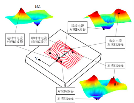
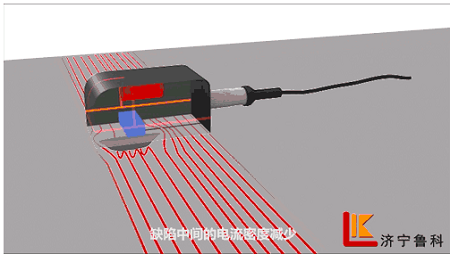
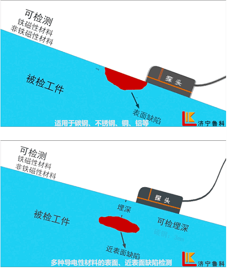
ACFM indicates is part of the burgeoning electromagneticsm NDT technology that has been developed based on ACPD (Alternating Current Potential Drop), and it can be used to realize provide fast detection of the surface and near-surface defects forof all ferromagnetic and nonferromagnetic conductive materials. The principle behindof ACFM is that the exciting coil induces the an even alternating current in the workpiece, and thise induced current then generates disturbances in magnetic fields in defect locations, indicating such as cracks and corrosion, thus the distortion of space magnetic field is caused and the detection and evaluation of the defect is realized by detecting the distorted magnetic field. The induced current is a uniform field, and thus there is noe magnetic field is not distortioned when there exists are no defects in the materials being tested. However, when there exists the a defect is present, the current bypasses the endpoint and bottom of the defect and, causinges the a trough in magnetic field Bx (i.e. the field parallel to the workpiece surface and perpendicular to the direction of the current direction) in the direction of X. It also causes a trough in the center of the defectt center, manifesting revealing the length of the defect through the, alternating peaks and valleys in the magnetic field By (i.e. the field parallel to the workpiece surface and along in the direction of the current direction) in the direction of Y, and through the wave crest and trough in magnetic field Bz (i.e. the field perpendicular to the workpiece surface) in the direction of Z, at the in defect’s endpoint. The wave crest and trough manifests provide the information about that enables the ACFM to determine the length of the defect.
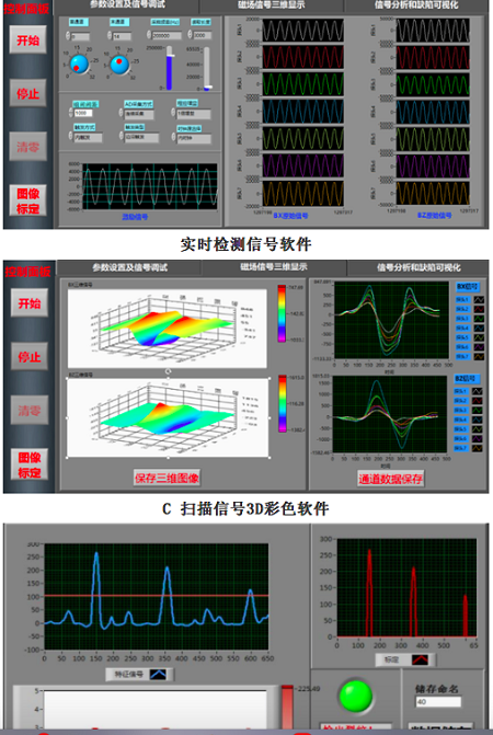
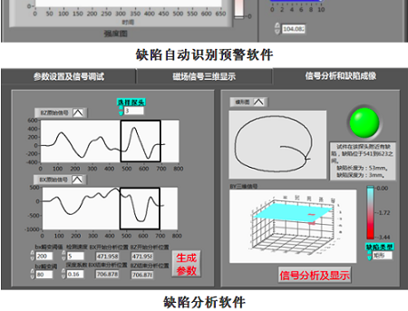
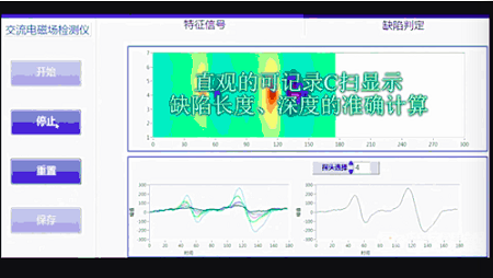
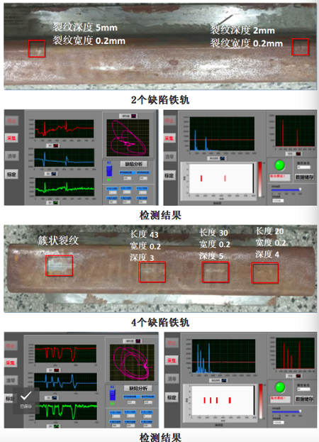
The magnetic field component is zero when the workpiece in intact, but when there is a crack in it, there will be variations in the magnetic field at the surface of the workpiece. When this happens, the probe in the instrument inputs the detected signals into its computer for analysis, and the location, length and depth of the crack will be displayed in real-time through its software.
BZ corresponds to the start and end points of the crack. The wave crest will emerge at the start and end points when the probe passes by the crack, thereby revealing the length of the crack.
BX corresponds to the current density. As the crack density decreases when the depth of the crack increases, this enables the depth of the crack to be detected.
III. Features and Strengths of Intelligent ACFM
1. ACFM can be used effectively on a variety of conductive materials, and its main application will be the rapid and accurate detection of surface and near-surface defects on both ferromagnetic and nonferromagnetic materials.
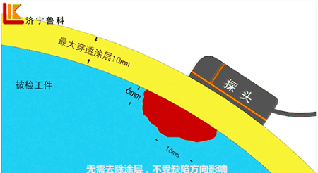
2. Its detection method, which penetrates the surface coating of the workpiece without damaging it, saves time and cost in comparison to methods that eliminate surface coating. The probe doesn’t need to form direct contact with the workpiece that is being examined to detect defects. The maximum distance between the probe and the studied workpiece should be 10mm, and the probe can function effectively when the workpiece has a non-conductive coating of 10mm or less, such as those seen in spray coatings, paint coatings, epoxy resin glue layers and asphalt layers.
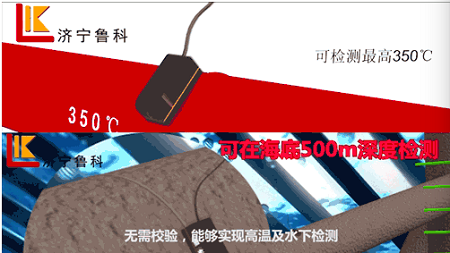
3. It can detect non-fatigue cracks in surfaces with temperatures of up to 350℃, and on materials up to 500m depth in water.
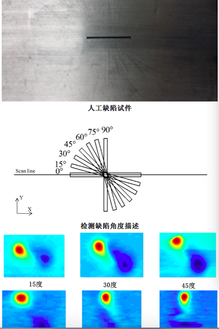
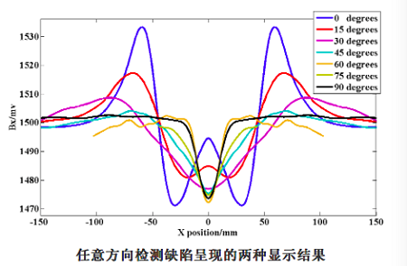
4. It cCan detect the crack defects in any direction.
5. There is accurateIt has a sound theoretical basis grounding,and is mathematically modelled available, and the information about the length and depth of cracks can be provided at the same time without the need for a test block check test.
6. With a portable detection system such as ACFM, the labor intensity of the detection staffs can be reduced and detection the efficiency of detection can be improved. The probe can be used for rapid scanning. There is , and there are no problematic after effects produced by the on detection method, and necessity insuch as demagnetization or the need forand surface cleaning, etc.
7. The detection system is comprised of the main engine and probe. No any consumables, mediums orand coupling agents are required for detection, so thesaving on costs compared to those that require any of these things expense is saved.
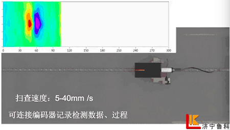
8. It cCan be connected to the an encoder to record and store the detection data in real time, record the detection process and results, and allow for the recording and replaying of the any defects detected, together with the and calculation ofe their defect sizes. The scanning speed reaches ranges from 5-40mm/s.
9. The dDisplay features aed based on 3D C-scan signal color imaging mode, automatic defect identification and a warning mode.
10. Compared to the traditional surface flaw detection methods including magnetic particle testing, penetrant testing, and eddy current testing.
|
|
ACFM |
MT |
PT |
ET |
MFL |
|
Material |
Conductive |
Ferromagnetic |
Any |
Conductive |
Ferromagnetic |
|
Surface Flaw |
yes |
yes |
yes |
yes |
Not sensitive |
|
Flaw Depth Measurement |
Yes |
No |
No |
Yes |
Yes |
|
Near Surface |
Yes |
Yes |
No |
No |
Yes |
|
Maximum Flaw Depth |
Al 10mm Stainless steel 5mm Carbon Steel 3mm |
Carbon Steel 3mm |
No |
—— |
Transverse crack |
|
Measurable flaw size |
Deptch≥0.5mm |
Unlimited |
Unlimited |
—— |
—— |
|
Testing through coating |
Yes |
No |
No |
Yes,but not good |
Yes |
|
Surface clean before testing |
No need |
Need |
Need |
No Need |
Need |
|
Record testing process |
Yes |
No |
No |
Yes |
Yes |
|
Recording testing result date mode |
Parameter,curve and C scan |
Picture or video |
Picture or video |
Parameter,curve and C scan |
Parameter,curve and C scan |
|
Underwater Testing |
Yes |
No |
No |
Yes |
—— |
|
HT Testing |
Yes |
No |
No |
Yes |
—— |
|
Calibration before Testing |
No need |
Need |
Need |
Need |
Need |
|
Operating Difficulty |
Medium |
Medium |
Low |
High |
High |
|
Operating Efficiency |
High |
Medium |
High |
High |
High |
|
After Testing |
No need clean |
Need clean |
Need clean |
No need clean |
Need Demagnetising |
|
Need consumables |
No |
Yes |
Yes |
No |
No |
|
Array probe |
Yes |
No |
No |
Yes |
Yes |
V. Test data forof Intelligent ACFM:
1. Detection of ng surface defects in any direction: this represents a break through, overcoming the restrictions seen inof traditional ACFM and MFL (magnetic flux leakage testing) in crack detirectorsion, and have higherwhich have detection weaker sensitivitiesy for detectingin cracks in any direction.
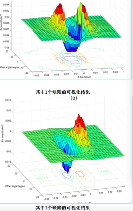
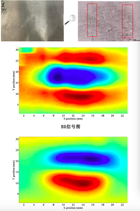
2. Near-surface flaw detection:
|
Testing No. |
1 |
2 |
3 |
4 |
5 |
Actual Value |
|
Defect Length |
26 |
26 |
25 |
28 |
28 |
30 |
|
Defect Depth |
2.73 |
2.95 |
2.67 |
2.56 |
2.87 |
3 |
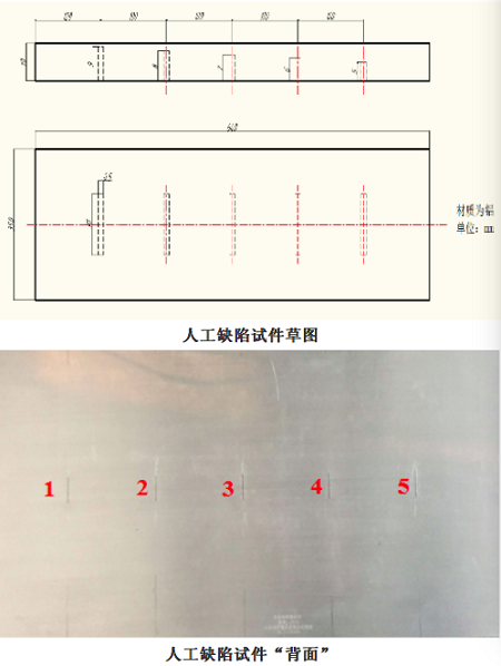
For a defect with a length of 30mm and a buried depth of 3mm in an artificial defect test piece, the data concluded through five repeated detection tests that the inversion accuracy of our portable ACFM instrument exceeds 85%, which is close to the size of the defect.
3. Detection of the surface defect of the stainless steel weld joint:
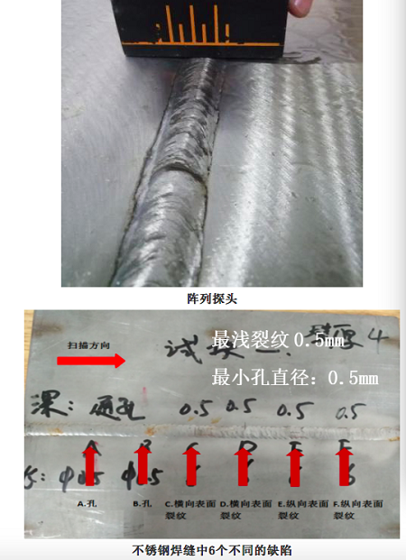
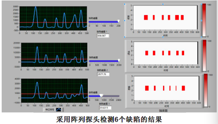
The results of the detection of six defects with an array probe
Primary scanning and covering of the weld joint and detection of heat-affected zone crack with array probe
4. Detection of the surface defect of athe pipeline
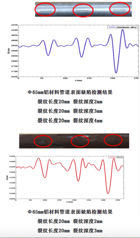
5. Detection of the crack defect of a natural cluster
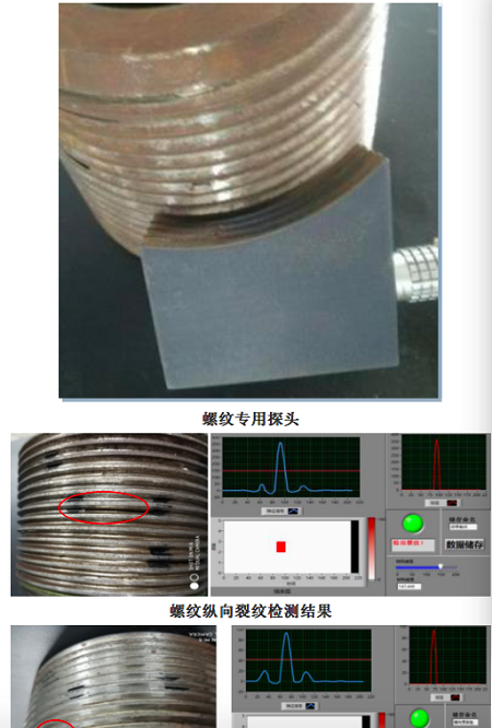
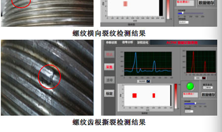
6. Thread flaw detection
7. Rail surface flaw detection:
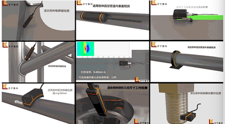
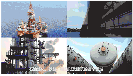
VI. Application Fields of ACFM
VII. Optional Detection Probes
|
Type |
Pen Probe |
Standard Probe |
Standard Probe |
Array Probe |
Screw Probe |
Customise Probe |
|
Model |
BZ1-10 |
PM1-10 |
PM2-20 |
PM8-70 |
LS1-10 |
|
|
Channel |
1 |
1 |
2 |
8 |
1 |
|
|
Testing Range |
10mm |
10mm |
20mm |
70mm |
10mm |
|
|
Diemansion |
80*30*20mm |
68*39*48mm |
68*39*48mm |
108*75*48mm |
Depends on the screw |
|
|
Probe Cable |
3m, upgrade up to 30m |
3m, upgrade up to 30m |
3m, upgrade up to 30m |
3m, upgrade up to 30m |
3m, upgrade up to 30m |
|
|
Encoder |
N |
Y |
Y |
Y |
Y |
|
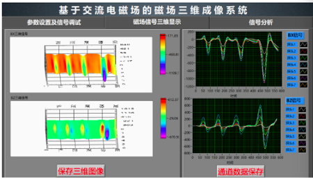
Intelligent quantitation, 3D profile visual software
VIIIIX. Intelligent Detection Software
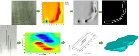
The software mainly includes a characteristic signal module (Bx, Bz and butterfly plot), a C-scan imaging module, an intelligent determination module, a defect analysis module, a morphology visualization display module, and a statement module. A sSingle probe can dynamically display the characteristic signals of the defect in real time, and an array probe can be used to realize produce a C-scan imaging display showing theof defect’s distortion magnetic of the magnetic field. As for the intelligent determination module, Tthe alarm threshold value in the intelligent determination module can be set varied according toto pick up different sizes ofthe defect size, and the. dDefect analysis module can be used to realize enable the selection and quantitative evaluation of the characteristic signals. The mMorphology visualization module can be used to realize 2D or 3D profile reconstructions through the intelligent algorithm, whilst. the sStatement module can be used to save the data and image results, as well as toand generate detection reports.